")
")
")
")
")
")


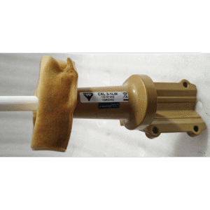
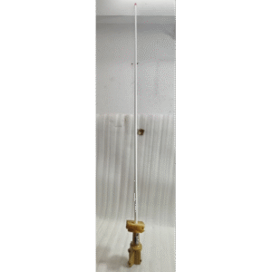

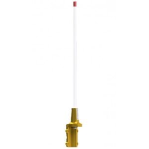
The Procom Pro CXL 3-1LW is a very high-quality, low-profile communications antenna designed for fixed installation on aircraft. It operates in the VHF (Very High Frequency) Aeronautical Band, which is used for all primary air-to-ground and air-to-air voice communications.
The “LW” in the model number typically stands for Low Weight or Light Weight, indicating it’s designed to minimize mass, a critical factor in aviation.
Key Features
-
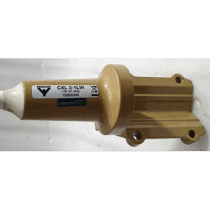
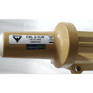
Aeronautical VHF Band: Tuned specifically for the 118-137 MHz range, which is exclusively for aviation communication (e.g., talking to Air Traffic Control, Tower, Ground, and other aircraft).
-
Low Profile & Lightweight: Designed to have minimal aerodynamic drag and weight impact on the aircraft, a key requirement for all avionics components.
-
Durable Construction: Built to withstand extreme environmental conditions, including high airspeeds, vibration, temperature fluctuations, UV exposure, and corrosion.
-
Low VSWR: Features a optimized Voltage Standing Wave Ratio (VSWR) across its frequency range. A low VSWR (close to 1:1) means maximum power is transmitted from the radio to the antenna instead of being reflected back, ensuring clear transmission and reception.
-
Composites Base: Often features a robust composite base that is both strong and non-corrosive.
-
Lightning Protection: Likely includes provisions or is designed to be part of the aircraft’s overall lightning protection system.
Technical Specifications
| Parameter | Specification | Notes |
|---|---|---|
| Manufacturer | Procom (A well-regarded manufacturer of professional antennas, especially in the aviation and marine sectors). | |
| Model Number | Pro CXL 3-1LW | “CXL” is likely the series, “3-1” may refer to the gain or design, “LW” for Light Weight. |
| Part Number | 1326330400 | This is the specific manufacturer part number for ordering. |
| Type | VHF Communications Antenna (Blade Antenna) | |
| Frequency Range | 118 – 137 MHz | The standard aeronautical VHF band. |
| Bandwidth | 19 MHz | Covers the entire allocated band. |
| VSWR | Typically < 1.5:1 across the entire band | Excellent efficiency. |
| Impedance | 50 Ohms | Standard for all commercial and aviation radio equipment. |
| Polarization | Vertical | Standard for VHF air communications. |
| Gain | Likely near 0 dBi (Omnidirectional) | Provides a consistent “doughnut” shaped radiation pattern for communication regardless of aircraft attitude. |
| Power Handling | 100 Watts (or more) | Far exceeds the output of any standard aircraft VHF radio (which are usually 10-25W). |
| Connector Type | SO-239 (UHF) or TNC | A connector compatible with standard RG-58 or similar coaxial cable. The specific type should be confirmed. |
| Mounting | Flush Mount | Requires a specific hole pattern to be drilled into the aircraft’s skin. |
| Height / Profile | Low Profile (Specific height in inches/mm would be in the datasheet) | Designed for minimal drag. |
Application & Usage
-
Primary Use: Aircraft VHF Communication. This is the primary antenna for the #1 or #2 VHF COMM radio in an aircraft.
-
Installation: It is a permanent, flush-mounted antenna typically installed on the top or bottom of the aircraft’s fuselage for optimal signal coverage.
-
Typical Aircraft:
-
General Aviation (Piston singles and twins like Cessnas, Pipers)
-
Business Jets
-
Helicopters
-
It may also be used on ground-based equipment at airports.
-
Important Notes
-
Certification: This is a FAA-PMA (Parts Manufacturer Approval) part. This means it is certified as an airworthy replacement for original equipment on specific aircraft models. It is not a generic consumer antenna.
-
Professional Installation Required: Installation on an aircraft MUST be performed by a licensed aircraft mechanic (A&P). This includes:
-
Drilling precise holes in the airframe.
-
Sealing the installation to prevent water ingress.
-
Properly routing and connecting the coaxial cable.
-
Logging the installation in the aircraft’s permanent records.
-
-
Performance: The performance of any antenna is highly dependent on a proper ground plane (the aircraft’s metal skin). Installation location is critical for optimal performance.
-
Maintenance: Like all external aircraft components, it must be inspected during regular aircraft maintenance cycles for damage, integrity, and corrosion.
Where to Find More Information
-
Procom (a division of ADC USA, Inc.): The manufacturer’s website or product catalog will have the official technical datasheet, installation drawing, PMA eligibility list, and STC (Supplemental Type Certificate) information.
-
Aircraft Spruce & Specialty Co.: A major supplier of aircraft parts; their website often has detailed specs and PMA information for products like this.
-
Official Documentation: The part number 1326330400 is the key to finding the exact installation manual and PMA paperwork, which are absolutely essential before purchase and installation.