- AUTOMATION EQUIPMENT
- DIGITAL CONTROL
- ELECTRICAL ITEMS
- AMPLIFIER & UPS
- BATTERY CHARGER & INVERTER
- CIRCUIT BREAKER & BLOCKS
- CONTROL UNIT
- ELECTRIC CONTROLLERS
- FIRE ALARAM SYSTEM
- FUSES & CAPACITOR
- HEADPHONE & SPEAKER
- HMI & DISPLAY
- MISC ELECTRICAL
- PCB
- PLC SYSTEMS
- POWER SUPPLY
- PRINTER & CPU
- RELAY
- SENSORS
- SERVO DRIVES & MOTORS
- TELECOME & COMMUNICATION
- THERMOSTAT
- MACHINERY
- SENSORS
- UNCATEGORIZED
")
")
")
")
")
")
")
Hotline Order:
(+91) 97257 54777
Email ID:
shipnavstore@gmail.com

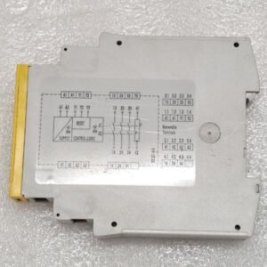
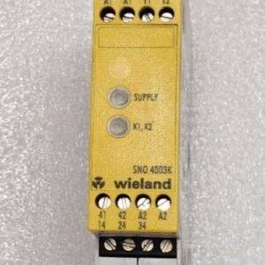
WIELAND SNO 4003K-A SAFETY RELAY R1.188.0900.1 17:26
₹14,098.00
| Product Conditioned | USED |
|---|
Free Shipping apply to all orders over $199
Guaranteed Money Back in 30 days return.
24/7 Customer Support
Share:
 WIELAND SNO 4003K-A SAFETY REL...
₹14,098.00
1 in stock
Hotline Order:
(+101) 5620 - 8155
Email ID:
xstore@support.com
Key Product Identification
-
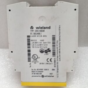
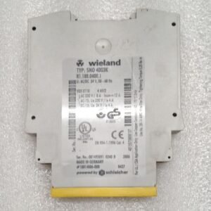
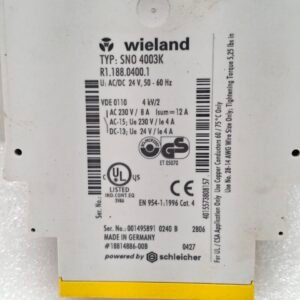
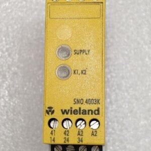
Main Model: SNO 4003K-A
-
Order Number / Article Number: R1.188.0900.1
-
SEO Description: A single-channel safety monitoring relay with guard locking, designed for monitoring interlocking devices with a solenoid-actuated lock on safety gates and guards. It ensures the machine cannot restart until the guard is closed and locked, and prevents the lock from releasing while dangerous machine motions are present.
Primary Function and Purpose
This safety relay is used to interface with a safety gate or guard that is equipped with a locking mechanism. It serves two main purposes:
-
Monitoring: It monitors the status of the safety gate’s switch (is it open or closed?).
-
Locking Control: It controls an electromagnetic lock that prevents the gate from being opened while the machine is in a hazardous state.
A classic example is a machine with a long “run-down” time (e.g., a press brake, a large saw, a robot cell). The relay ensures the guard door remains locked shut until the machine has come to a complete stop and it is safe to open. It also ensures the door is closed and locked before the machine can be started.
Key Features
-
Single-Channel Monitoring: Designed for monitoring one safety contact (e.g., one guarded door). For higher safety levels (like PL e / Cat. 4), a dual-channel device would typically be used.
-
Guard Locking Function: Integrated control for a DC solenoid lock.
-
Manual Release (Optional): The “-A” variant often includes a manual release function (e.g., a button or key switch on the device) to unlock the door in case of emergency or for maintenance, often under specific safety conditions.
-
Forced-Guided Relays (Positively Driven Contacts): The internal safety relays are mechanically linked. This means the Normally Open (NO) and Normally Closed (NC) contacts cannot be closed at the same time, a fundamental requirement for safe circuit design. This prevents contact welding from creating a dangerous situation.
-
LED Status Indication: Clear LEDs to indicate power status, input circuit status, and output relay status for easy diagnostics.
-
Compact Design: Designed to fit in standard DIN rail enclosures.
-
Safe Time Delay: Upon receiving a signal to close the guard, there is a built-in delay before the locking mechanism is energized. This ensures the guard is fully closed before it can be locked.
Technical Specifications (Typical)
-
Supply Voltage: 24V AC/DC (common for this series)
-
Max. Locking Solenoid Voltage: Typically 24V DC
-
Contact Configuration: Several safety-rated (force-guided) contacts, e.g.:
-
2 NO (Normally Open) Safety Contacts: Used to control the main machine power (e.g., contactor coil circuit).
-
1 NC (Normally Closed) Safety Contact: Often used for feedback or a second channel.
-
1 AUX (Auxiliary) NO Contact: Non-safety-rated, used for status signals to the PLC or indicator lamps.
-
-
Safety Standards: Complies with EN 60947-5-1, EN 60204-1.
-
Safety Rating: Suitable for applications up to PL c / Category 2 as per EN ISO 13849-1 (when used as directed in the manual with appropriate components).
Typical Wiring and Operation
-
Inputs: The safety circuit from the guarded door’s switch(es) is connected to the A1/A2 terminals.
-
Outputs:
-
The safety contacts (13-14, 23-24, etc.) are wired in series to de-energize the main machine contactors.
-
The locking output (Y1/Y2) is connected to the solenoid lock on the guard door.
-
-
Sequence:
-
To Start: The guard door must be closed (activating the switch). The SNO relay will then energize the lock and, after a short delay, close the safety contacts, allowing the machine to start.
-
During Operation: The door is locked shut.
-
To Stop: A separate stop button is pressed. The safety contacts open, stopping the machine. The lock remains energized for a preset time (until the machine is safe), then releases, allowing the door to be opened.
-
Common Applications
This relay is used in various industrial settings where safe access control to hazardous areas is required:
-
Machine Tools: Press brakes, stamping presses, CNC mills.
-
Robotic Cells: Where robots have a large operating envelope and need time to stop.
-
Packaging Machinery: With large automated arms or sealing mechanisms.
-
Plastic & Rubber Machinery: Injection molding machines.
-
Automated Assembly Lines.
We're here when you need us
Get a Quick Quote
Complete our online form.
Call US
Speak to one of our team.
Live Chat
Send us a message
Speak to one of our team.